
An EPC is assessing a food-packaging factory in East Africa. The site already has a three-phase grid connection, rooftop solar PV and a diesel generator. The owner wants battery storage to support essential operations through power cuts and, where practical, reduce generator use.
The difficult question comes after the first outage: if the grid returns briefly and then fails again, will the battery be ready?
Using BESS for weak grids requires a plan for the loads, the equipment supplying them and the energy available between interruptions. Both cabinet BESS and containerized BESS need to be assessed against that plan.
The factory below is a hypothetical project walkthrough. Its operating sequence and energy figures are illustrative, not records from a GeePower installation or performance figures for a particular product.
Define what this factory actually needs to keep running
Start with the production team and the electrical team together. A list of equipment ratings will not tell the EPC which machines must continue, which can restart, or which supporting services a packaging line needs.
For this factory, the initial load schedule has three groups:
| Group | Example loads | Required behaviour | Who confirms it? |
|---|---|---|---|
| A: Interruption-sensitive | Controls, communications and production-data systems | Remain powered within an agreed interruption tolerance | Production and electrical teams |
| B: Selected production | A designated packaging line and its necessary auxiliary equipment | Continue or stop and restart in an agreed sequence | Production, maintenance and electrical teams |
| C: Deferrable | Other production lines and nonessential office loads | Remain off or be deferred during the backup duty | Factory operations team |
If the selected line needs compressed air or another shared service, include that demand. Leaving it outside the backup boundary could make the line unusable even while its main electrical feed remains energised.
Also distinguish the factory’s own load shedding—removing lower-priority demand—from scheduled load shedding imposed by the utility.
Record what the supply actually does: outage start times, duration, brief restorations and any measured voltage problems. Frequent interruptions mean the supply is unreliable. Technical grid strength is a separate issue. NERC’s guidance relates it to how sensitive the connection voltage is to changes in current injection. A history of power cuts alone doesn’t tell you the grid is weak in that technical sense.
The factory’s primary objective is now specific: support the selected loads through a defined outage duty. Electricity savings and reduced diesel operation remain secondary objectives.
Agree what must happen when the grid fails
Before discussing battery capacity, put the selected circuits, existing sources and proposed BESS on a site single-line diagram. Identify where the installation separates from the utility and which equipment supplies the critical-load bus—the circuits selected for backup.
Someone must establish voltage and frequency while that bus operates independently. Depending on the design, this could be a suitably configured grid-forming power conversion system (PCS) or another source, such as the generator. The operating description should identify that role and explain how the other connected sources follow it.
Each part has its own job: the battery management system supervises battery limits, the PCS converts power and operates in its supported modes, and the EMS or microgrid controller coordinates dispatch alongside the dedicated switching and protection equipment. Knowing the parts exist doesn’t tell you whether their interfaces work together.
The existing PV needs particular attention. Rooftop generation cannot be credited during an outage simply because daylight is available. The U.S. Department of Energy’s microgrid guidance explains that many solar systems disconnect when they detect islanding. You need to find out whether the factory’s PV inverter can participate in the proposed islanded system and how its output will be controlled.
Compare the complete transfer performance with Group A’s interruption tolerance. Battery response speed and a transfer-switch specification still leave open whether the load actually rides through.
If the project also needs to energise a completely dead bus without external support, specify black-start capability separately. Recovering a de-energised system and transferring an operating load without an unacceptable interruption are different duties.
Finally, trace the supply to controls, communications, switching and necessary auxiliary equipment during the outage. These systems need power for the proposed arrangement to function.
Protect the backup duty during normal operation
The factory also wants to use storage for solar self-consumption and lower-cost electricity. Those uses affect the energy left when an unplanned outage begins.
Agree what backup duty must remain available before setting a reserve SOC. State of charge describes how full the battery is; the useful reserve depends on the required load, duration, usable capacity, losses and operating limits. A percentage chosen without those inputs is difficult to defend.
For this factory, backup takes priority. Normal dispatch should therefore preserve the energy needed for the backup duty, unless the owner explicitly accepts a different level of availability.
That decision affects the savings proposal. Energy held for backup is unavailable for unrestricted daily discharge. If the commercial model assumes the same energy can always serve both purposes, the operating plan needs correction.
Define what happens when readiness falls below the required level. The operator should know which duty remains available, which discretionary discharge is restricted and whether another source or a reduced load plan is needed. A generic low-battery alarm gives too little information.
It also avoids false comfort at handover: a system can be healthy and communicating while lacking enough energy for the owner’s specified outage.
Work through the first outage with PV and generator support
The first outage tests the proposed operating sequence. Once the required isolation and supply conditions are in place, Group A must meet its continuity requirement. Group B follows its approved continuation or restart sequence. Group C stays outside the protected duty.
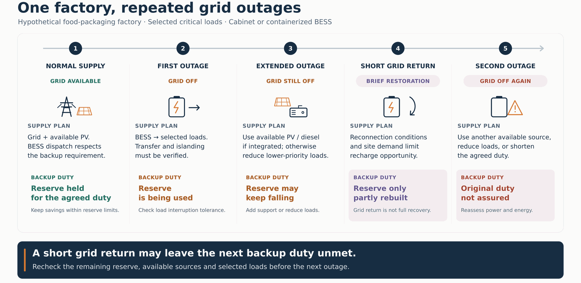
Keep the following sequence in view as the design develops:
| Point in the hypothetical sequence | Operating decision |
|---|---|
| Grid available | Preserve the backup duty while allowing agreed normal dispatch |
| First grid failure | Supply the selected circuits through the verified islanded arrangement |
| Outage continues or solar contribution falls | Assess remaining battery capability and arrange generator support or reduce demand |
| Grid returns for a short period | Meet reconnection conditions, establish charging headroom and restore reserve |
| Grid fails again before recovery is complete | Use the remaining capability and the agreed alternative-source or reduced-load plan |
During the first interruption, credit only the PV contribution that is available and supported by the islanded arrangement. Check the PCS and battery against load changes and starting requirements as well as the energy consumed.
If the outage extends, arrange generator support before the battery reaches a point where it cannot bridge the generator’s start and connection process. The trigger depends on remaining energy, demand and the time needed to make that source available.
Generator integration also needs a power balance. Supplying the selected loads and charging the battery at the same time requires sufficient available generator output, compatible equipment and coordinated controls. You can’t just add the planned charging rate on top without checking those conditions.
Agree how the generator takes over, whether sources operate together and how control responsibility changes. Commercial backup packages illustrate why this is a system task: SMA’s Backup architecture brings battery and PV inverters, grid connection, loads and an optional generator into a coordinated arrangement. Its capabilities are specific to that package.
If the generator is unavailable, the factory needs an agreed response: retain the highest-priority loads, reduce the supported demand or shorten the duty. The operating plan has to spell out the consequence.
Check recovery before promising the next outage
The utility returns, but production also starts drawing power again. The charging opportunity may be much smaller than the battery’s rated charging power suggests.
Separate four events: the grid returns, reconnection conditions are satisfied, charging becomes available, and the required backup reserve is restored. They need not occur together. If the supply repeatedly drops out, the usable recovery window may be shorter still.
Here is an energy-only check that shows why.
Illustrative AC energy check for the selected loads
| Item | Assumption or result |
|---|---|
| Energy available to the selected load boundary before the first outage | 160 kWh |
| Energy required for one agreed backup duty | 120 kWh |
| Remaining after that duty | 40 kWh |
| AC input headroom available to the charging path | 60 kW for one hour |
| Maximum energy restored under an optimistic, lossless assumption | 60 kWh |
| Maximum available before the next outage | 100 kWh |
| Energy needed to repeat the same duty | 120 kWh |
The starting 160 kWh is a hypothetical deliverable AC energy budget, already defined around the usable SOC range, losses and necessary auxiliary consumption. It is not battery nameplate capacity.
The assumed 60 kW charging headroom is what remains after concurrent site loads and auxiliaries. No additional PV or generator energy is credited, and the equipment involved is assumed available. Even with lossless recovery, the second duty is at least 20 kWh short. Actual conversion losses and charging limits can reduce recovery further.
This check isolates an energy shortfall; it does not establish power capability, transfer performance or a complete system design.
That leaves you with a concrete decision to take back to the owner. Your options are to provide another verified energy source, reduce the supported demand, shorten the next duty, or reassess the storage and recovery arrangement. Simply restoring the previous EMS schedule cannot supply the missing energy.
This short example is enough to show why completing the first outage doesn’t prove readiness for the second. For a full calculation of power, energy, reserve and charging requirements, use the two-hour commercial backup sizing guide.
Apply the operating plan to cabinet and containerized BESS
With the operating duty defined, you can compare physical arrangements against the factory’s distribution, space, maintenance and expansion plans.
A cabinet BESS arrangement is worth assessing where the site needs flexible placement or phased deployment. Establish whether power conversion is integrated or separate, how cabinets connect and which controls are shared. Locating cabinets in different areas does not automatically create independently supported load zones.
A containerized BESS arrangement is worth assessing for a centralised storage platform serving the selected distribution. Review transport and lifting access, foundations, cable routes, maintenance access and the integration boundary with external equipment. The enclosure itself doesn’t tell you whether the system delivers the required islanded behaviour.
For both candidates, examine what remains available when a unit is isolated or an important shared component is unavailable. Several cabinets may depend on one PCS or common bus. A containerized system’s fault isolation depends on its actual design. Compare remaining power and energy against the protected duty, rather than counting enclosures.
A separate published example, GeePower’s off-grid factory project in Mali, combines five 215 kWh cabinet ESS units with PV and diesel generation. That provides configuration background for a larger multi-cabinet system; it is distinct from the hypothetical factory here.
The 160 kWh operating budget above doesn’t decide the enclosure format, and neither does a general capacity threshold. Carry both candidates through the same load, recovery and interface requirements, then use the cabinet-versus-container comparison for the broader architecture decision.
Verify the operating scenarios before handover
The factory needs evidence that the agreed load behaviour is achievable. A normal status screen or a successful battery discharge does not demonstrate every operating duty.
Build the acceptance plan around the events already discussed:
- First outage: check the interruption experienced by Group A and the permitted continuation or restart of Group B.
- Short restoration followed by another outage: look at reserve reporting, charging limits, warnings and the supported load plan before full recovery.
- Generator or expected PV contribution unavailable: see how the system handles the resulting shortage and which demands take priority.
- Load starts, load changes or important control/communication faults: confirm equipment limits and the specified controlled response, including necessary auxiliary supplies.
Record the starting conditions, source availability, selected loads, SOC and power data, observed interruptions and agreed pass criteria. If a demonstration uses different loads or operating conditions from the required duty, record the limitation.
Allocate the evidence before testing. Request the manufacturer’s supported operating modes, interface information and factory test records. The EPC or system integrator should organise the site-specific functional description and commissioning evidence. Factory operations must confirm that the process behaviour and restart sequence are acceptable.
Factory tests support the equipment assessment. The site’s wiring, existing PV, generator, controls and actual loads still need to be considered together. Qualified project teams should plan and execute these tests under an agreed procedure.
By handover, the operator should know both the available duty and the action required when reserve or another source becomes unavailable.
Turn the findings into a site operating brief
You can now replace a broad request for industrial battery backup with a short document that the factory and equipment suppliers can work from.
Use the structure below for your own site. In this hypothetical example, the site conditions are assumptions. On a real project, mark an item Confirmed only when it has checked evidence and a named person responsible for that confirmation.
| Field | Entry for the hypothetical factory | Status and responsibility |
|---|---|---|
| Supply problem | Irregular outages, sometimes separated by brief restorations | Assumed; EPC checks records with facilities |
| Supported loads | Groups A and B, including the services needed by the selected packaging line | Assumed boundary; production and electrical teams confirm circuits |
| Interruption and restart | Group A’s tolerance and Group B’s restart sequence need agreement | Unknown; production and electrical teams |
| Existing sources and interfaces | Grid, rooftop PV and diesel generator; islanded compatibility not established | Assets assumed; interfaces checked by integrator and suppliers |
| Service priority | Backup takes precedence over discretionary discharge | Assumed project objective; owner confirms |
| Reserve and recovery | Required reserve, charging headroom and usable recovery windows need assessment | Unknown; EPC and system suppliers |
| Abnormal conditions and acceptance | Include repeated outages, unavailable generation and relevant equipment/control faults | Test conditions and pass criteria to be agreed by the project team |
Keep the evidence reference with each entry: a load record, drawing, inverter document, operating description or test report. Unknowns should have an owner and a next action. For the wider project package, continue with the BESS project requirements checklist.
For this factory, the next step is to confirm the load tolerances, source interfaces and recovery conditions before selecting a final configuration.
Bring that operating brief to GeePower’s C&I ESS project discussion. We can support cabinet or containerized BESS configuration and engineering discussions alongside the EPC or installer on your project. Include what is known, the evidence behind it and the questions still open, so the proposed equipment can be assessed against the duty your site actually needs.
Frequently Asked Questions
They’re two different problems. An unreliable grid has frequent interruptions, so you judge it from outage start times, durations, brief restorations and any measured voltage problems. A technically weak grid is about grid strength, which NERC relates to how sensitive the connection voltage is to changes in current injection. A history of power cuts alone doesn’t tell you the grid is weak in that technical sense.
It can support the loads you select, provided the system is designed and verified for that duty. Start by splitting the site into loads that must stay on, loads that can stop and restart, and loads that can wait. Then confirm which source sets voltage and frequency while the site is islanded, and compare the full transfer performance with what your most sensitive loads can tolerate. If you also need to energise a dead bus without external support, specify black-start capability separately.
Not automatically. The U.S. Department of Energy notes that many solar systems disconnect when they detect islanding, so you need to confirm that the factory’s PV inverter can take part in the islanded system and how its output will be controlled. Until then, credit only the PV contribution that is available and supported by the islanded arrangement.
There’s no universal percentage. Define the backup duty first: the required load, duration, usable capacity, losses and operating limits. Then set the reserve SOC from those inputs. If the same battery also serves solar self-consumption or lower-cost electricity, remember that energy held back for backup isn’t available for unrestricted daily discharge. In our example factory, backup takes priority, so normal dispatch preserves the energy needed for the duty unless the owner explicitly accepts otherwise.
Because recovery can be much slower than the grid’s return suggests. Once the utility is back, production starts drawing power again, so charging headroom may sit well below the battery’s rated charging power. In our hypothetical example, 160 kWh is available before the first outage and one duty uses 120 kWh. Even with 60 kW of headroom for one hour and no losses, only 100 kWh is available for the next outage, at least 20 kWh short. The figures are illustrative.
Neither format decides this for you. Carry both through the same load, recovery and interface requirements, then compare what remains available if one unit is isolated or a shared component fails. Cabinet BESS is worth assessing where the site needs flexible placement or phased deployment; containerized BESS suits a centralised storage platform, with transport, lifting, foundations, cable routes and maintenance access to review. Several cabinets can still depend on one PCS or common bus. For the wider decision, see our cabinet-versus-container comparison.
Turn your outage record into a BESS operating brief
Planning backup for a site with frequent outages? Share your load list and outage record, and we’ll discuss the configuration with you and your EPC or installer.