Case Overview
Historical Engineering Case Study · 2023
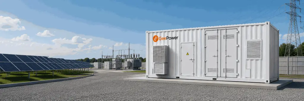
A containerized, grid-connected BESS designed for long-duration peak shifting, tariff optimization and controlled grid interaction. 250kW rated power. 1050.6kWh nominal capacity.
Archive Note: This case is based on GeePower engineering records from 2023. Detailed system configuration and operating logic have been retained, while the original site location and project photography are not included in the archived materials currently available.
System at a Glance
Parameter
| Configuration |
Rated Power |
250kW |
Energy Capacity |
1050.6kWh |
Maximum Charge / Discharge Power | 275kW |
Battery Chemistry | LiFePO₄ |
Battery Cell |
3.2V / 90Ah |
Battery Architecture |
228S4P × 4 |
Grid Output |
AC 400V / 50Hz |
Enclosure |
40-ft container |
Core Systems | Battery, BMS, PCS, monitoring, thermal management and fire protection |
The Engineering Objective
Peak shifting on a commercial or industrial site is straightforward as a concept. The engineering is less so.
This system needed to deliver approximately 1MWh of usable storage capacity with around 250kW of controlled charge and discharge power — and do it within a containerized architecture that integrated battery management, power conversion, monitoring and protection as a single deployable unit.
The design treated these requirements as interconnected. Battery, PCS, BMS and auxiliary systems were specified together to operate as an integrated BESS, not as independent components assembled later on site. That distinction shaped every downstream engineering decision.
Why 250kW / 1050.6kWh?
At 1050.6kWh nominal capacity and 250kW rated power, this is approximately a four-hour storage system.
That ratio fits applications where charging happens progressively over several low-tariff hours and discharging covers the high-tariff window — which describes most time-of-use optimization and peak shaving scenarios. The sizing here supported peak shaving, load shifting, time-of-use tariff optimization, controlled grid charging and discharging, and a measurable reduction of high-tariff grid consumption.
The specific numbers belong to a 2023 project. The sizing logic is portable. Optimal capacity for any modern BESS depends on site load profile, tariff structure, grid limits and required operating strategy. The four-hour profile reflects one specific set of those parameters.
Battery Architecture
The system used 3.2V / 90Ah LiFePO₄ cells. At module level, the configuration was 6S4P:
- 6 cells in series: 19.2V
- 4 cells in parallel: 360Ah
Scaling from module to system:
228S4P × 4 → 729.6V × 360Ah × 4 ≈ 1050.6kWh
The 228-series string reached the required system voltage. The four-parallel-branch arrangement delivered the capacity. The four-unit battery structure gave the architecture its modularity — allowing the system to be assembled, tested and transported as discrete sections.
This is worth reading as more than a calculation. Cell selection determines system voltage range, which constrains PCS design. Parallel branch count affects capacity and fault tolerance. Battery unit count determines physical layout and serviceability. Decisions made at cell level propagate through the entire architecture.
Integrated System Architecture
The system operated on a clear electrical hierarchy:
Grid ↔ PCS ↔ DC Bus ↔ Battery System
The BMS supervised the battery throughout. The monitoring and control layer coordinated operating status, alarms and data across all subsystems.
Battery System
LiFePO₄ modules and racks provided the energy storage capacity.
Battery Management System
The BMS monitored cell and pack voltage, current, temperature and state of charge, and provided protection against abnormal operating conditions across all battery units.
Power Conversion System
The PCS handled bidirectional power conversion between the battery DC system and the AC grid, operating at 400V / 50Hz on the AC side.
Monitoring and Control
Operating status, charge and discharge conditions, alarms and system data were managed through the control system.
Thermal Management
Temperature control equipment maintained the battery environment within the required operating range across varying ambient and load conditions.
Fire Protection
A dedicated fire-protection system was integrated into the container as part of the core safety architecture — specified alongside the battery and electrical systems, not added later.
Charging and Discharging Logic
The operating strategy centred on scheduled grid charging and discharging.
During low-tariff periods, the PCS charged the battery from the grid within configured power limits. The BMS monitored voltage, current, temperature and state of charge continuously throughout. When high-tariff periods began, stored energy discharged through the PCS to supply the site load — reducing what had to be purchased from the grid at peak rates. Outside these windows, the system held standby: no charging or discharging, but BMS and control system monitoring continued uninterrupted.
If abnormal conditions appeared at any stage — battery, PCS or system level — protection logic could interrupt operation before the condition escalated.
The result was a system that functioned as an active energy management asset. Not a battery bank with a timer, but a coordinated control architecture where every subsystem had a defined role in the operating cycle.
Containerized Integration
The complete system was packaged into a 40-ft container.
Battery racks, electrical equipment, monitoring systems, cooling and fire protection were all integrated into the enclosure. The archived engineering specification included requirements for weather-resistant structural steel, corrosion-resistant coating, thermal insulation, fire-resistant materials, controlled internal temperature, and electrical protection and isolation.
Containerized integration served two engineering purposes. It simplified transportation. And it allowed the major subsystems to be assembled, wired and tested before the container reached site — so what was delivered was an integrated BESS, not a collection of components requiring field assembly under variable conditions.
Illustrative 2023 Tariff Scenario
The archived engineering records evaluated the system against a peak-valley electricity price optimization scenario.
Historical operating assumptions:
- 945.54kWh grid energy drawn for charging
- 813.16kWh delivered during discharge
- $0.051/kWh off-peak electricity price
- $0.182/kWh peak electricity price
Single charge-discharge cycle calculation:
Charging cost
945.54kWh × $0.051/kWh ≈ $48.22
Value of discharged electricity
813.16kWh × $0.182/kWh ≈ $147.99
Illustrative tariff-spread value
Approximately $99.8 per cycle
The arithmetic demonstrates why a meaningful tariff spread creates economic logic for battery storage. The wider the gap between off-peak and peak rates, the stronger the case — bounded by actual system efficiency, usable depth of discharge and cycle life.
Important: This is an illustrative calculation based on historical 2023 project assumptions, not a current savings guarantee. Actual project economics depend on local electricity tariffs, system efficiency, usable depth of discharge, cycling frequency, battery degradation, demand charges, operating strategy and other site-specific factors.
What This Engineering Case Demonstrates
The numbers in this case belong to 2023. The design principles don't have an expiry date.
Battery capacity must be matched to the site's operating objective — not estimated from industry averages. PCS power should reflect the required charge and discharge profile, not simply the battery nameplate. BMS, PCS and monitoring systems need to function as an integrated control architecture; co-location without integration is not the same thing. Thermal management and fire protection are fundamental to BESS design. And project economics need to be evaluated against the actual site load profile and tariff structure, not illustrative scenarios that may not match the deployment context.
Current GeePower systems use newer battery platforms, updated architecture and more capable control technologies. The engineering approach — designing the full system around the operating objective rather than sizing the battery in isolation and filling in the rest — remains the same.
Planning a Similar C&I Energy Storage Project?
GeePower currently provides cabinet and containerized battery energy storage systems for commercial and industrial applications.
System capacity, PCS power, battery configuration, EMS strategy, communications and project-specific requirements can be evaluated according to the application and target market.
→ → [Commercial ESS Solutions]