
For the illustrative commercial and industrial loads in this article, the preliminary requirement for two hours of backup is about 1.66 MWh of initial nominal DC battery energy and 616 kW of steady-state AC power. The calculation includes load allowances and auxiliaries and assumes a 90%–10% SOC window, 95% discharge efficiency and 80% target capacity retention.
Eight 215 kWh battery cabinets meet the simplified energy requirement. The worked example below shows how to calculate energy and power separately, check starting SOC and recharge, and determine whether peak shaving can share the battery while preserving the specified backup reserve.
Define the backup duty and its inputs
The background is GeePower’s 800 kW / 1.72 MWh solar-storage hybrid project in Africa. The published configuration comprises eight 215 kWh battery cabinets, rooftop solar, centrally integrated PCS, MPPT and STS equipment, and a centralized energy management system (EMS). The system is described as supporting grid-connected and off-grid operation.
This is a battery-cabinet arrangement with centralized power conversion and control. The cabinet count does not establish the number of power conversion systems (PCS).
About this example: The project supplies the background architecture and scale. The loads and operating assumptions below are illustrative, not measured site records or a reconstruction of the original design decisions.
Specify what remains powered
For this calculation, the duty is to supply a defined critical-load bus for two hours during a nighttime grid outage. Noncritical loads are disconnected. Solar and other generation contribute no energy during that period.
Power, measured in kW, describes the rate at which the loads consume energy. Energy, measured in kWh, accumulates over the time those loads operate.
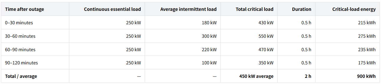
The load categories illustrate operating combinations. For a real site, identify the critical circuits and their operating sequence before extracting the backup profile.
NREL identifies critical loads and outage duration as sizing inputs; critical loads may differ from normal site consumption (Battery Storage for Resilience, p. 3).
Keep the calculation assumptions together
State of charge (SOC) describes how full the battery is relative to its capacity at that time. Starting at 90% SOC and stopping at 10% provides an 80-percentage-point operating window.
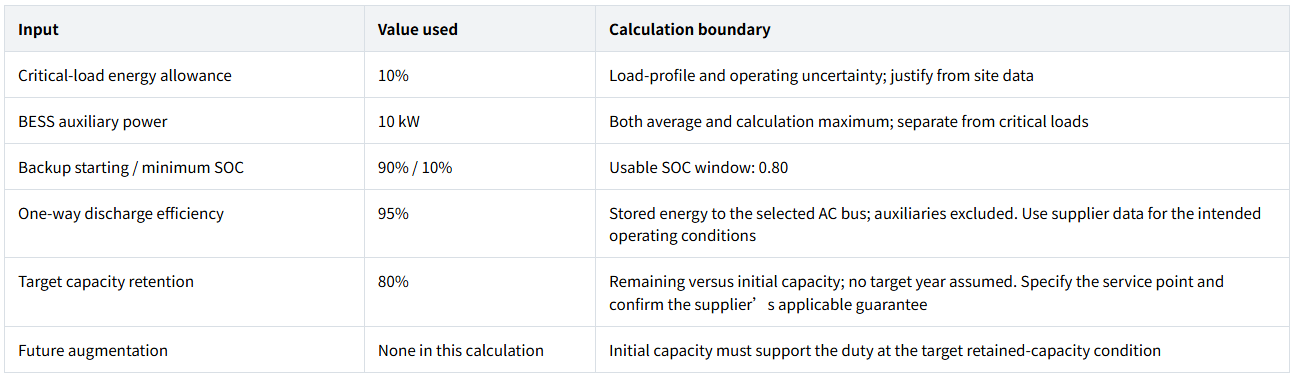
These are illustrative inputs, not defaults or product guarantees. All required equipment is assumed available, with no N−1 guarantee or additional environmental derating. Actual temperature, altitude and equipment limits still require checking.
Auxiliaries use the same AC boundary throughout; a different supply path requires a corresponding energy balance. Power and recharge assumptions appear at their calculation steps.
Obtain interval data for energy and demand analysis, together with the finer measurements or equipment information needed for power and starting checks.
Calculate the energy requirement before choosing battery capacity
Add the load energy, allowance and auxiliaries
For each interval, multiply average power by its duration:

Auxiliaries consume 10 kW × 2 h = 20 kWh. Apply the 10% energy allowance to the critical loads, then add the separately specified auxiliaries:

The allowance covers uncertainty in the selected load profile; another unexplained overall safety factor would obscure what the calculation covers.
Convert delivered AC energy into initial nameplate DC energy
Here, nameplate energy means the battery’s initial nominal DC energy. Only part of it is available between the chosen SOC limits, some energy is lost along the discharge path, and the design must still work when retained capacity reaches 80%.
The simplified relationship is:

Here, (ΔSOC) is the usable SOC window, (ηdis) is one-way discharge efficiency, and (r) is the target capacity-retention fraction.
Substituting this example’s inputs:

The preliminary requirement is about 1.66 MWh of initial nameplate DC energy, for this two-hour duty, a 90%–10% SOC window, 95% discharge efficiency and 80% target capacity retention.
The two factors of 0.80 represent different conditions. The SOC window limits how much of the battery’s available capacity is used during the event. Capacity retention describes how much capacity remains relative to the initial battery.
For an initial-capacity-only requirement (r = 1), the same calculation gives about 1.33 MWh; the larger requirement comes from the 80% capacity-retention target, without assigning it to a specific year or degradation curve.
Check the supplier’s energy definition before applying these factors. A guaranteed usable AC energy figure may already include an SOC window, conversion losses or a retained-capacity condition. Confirm those boundaries before deducting them again. The formula above applies to the initial nominal DC energy definition used here.
Size power separately and check what the PCS must support
The load table averages 450 kW over two hours. Selecting power conversion equipment on that average would miss the separately specified 550 kW simultaneous running load.
Add auxiliary demand and the 10% steady-state planning allowance, justified against uncertainty in the simultaneous running load:

Using the example’s aggregate power factor of 0.9:

This establishes a 616 kW steady-state planning requirement, corresponding to approximately 684 kVA under the simplified power-factor assumption. Both active and apparent power need to be checked against the equipment’s capability in the required operating mode.
The published 800 kW system is a candidate for further assessment. Its rating alone does not establish its continuous islanded kW or kVA capability, nor prove that the battery can supply the necessary DC power at the relevant SOC, retained capacity and site conditions. This calculation also does not establish that 800 kW is the minimum required rating.
Starting and transfer requirements need their own evidence
A 10% steady-state allowance does not establish motor-starting capability. For a pump, compressor or other significant starting load, obtain the starting power or current, duration, starting method and sequence, then compare them with the battery and PCS limits.
NLR’s Black Start explanation describes the need for a voltage reference from grid-forming equipment and highlights the transient inrush challenge posed by inductive loads. A steady-state kW calculation does not answer those questions.
Confirm grid-forming capability, transfer time and any continuity arrangement against the loads’ interruption tolerance. Black start, if required, needs separate evidence. An STS alone does not establish complete transfer performance.
Test the cabinet configuration, starting SOC and recharge window
Compare seven cabinets with eight
With 215 kWh per cabinet, the energy calculation gives:

Test both the rounded candidate and the next smaller arrangement under the same assumptions. Deduct the 20 kWh of backup auxiliaries before comparing the remaining energy with the 990 kWh design critical-load requirement:
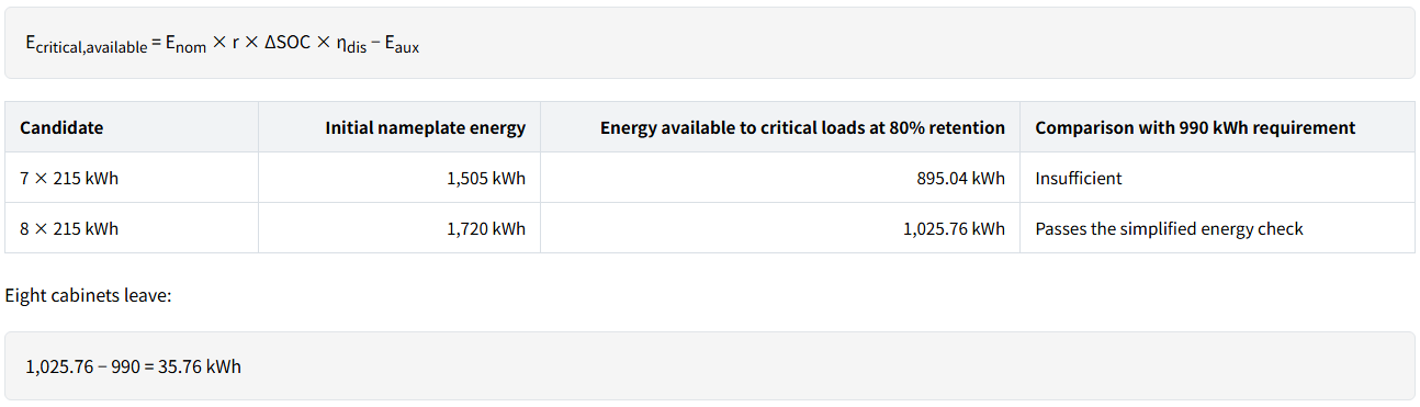
That remaining energy is measured against the design load after its 10% allowance. It does not demonstrate coverage of environmental derating, starting limitations or an equipment failure.
Cabinet sizing by division establishes an energy candidate. Confirm the DC voltage range, permitted cabinet connections, current limits, BMS–PCS communication and protection compatibility before treating it as an orderable configuration.
Check the SOC required when the outage begins
A battery can satisfy the nameplate calculation and still be insufficiently charged when needed.
For the eight-cabinet candidate at 80% capacity retention, the minimum starting SOC required for the design duty is:

The selected 90% backup readiness level therefore supports this simplified energy requirement. It is the operating state that must be maintained for the duty; it is not another reserve factor to deduct from the calculation.
SAM’s Grid Outage documentation treats critical loads, outage timing and minimum SOC as explicit modeling inputs. For a real site, test relevant outage start times and the SOC left by normal dispatch. A favorable two-hour window cannot establish availability throughout the operating schedule.
Check whether the battery can recover before the next duty
Use a four-hour recovery window. The assumed 95% one-way charge efficiency relates AC charging input to restored stored energy, excluding auxiliaries; obtain supplier data for the intended charging conditions.
After delivering the design 1,010 kWh AC, the battery has lost more stored energy than that because of discharge losses. Charging must replace that stored energy and incur charging losses.
With 95% efficiency in each direction, the required AC input to the charging path is:

Charging auxiliaries use another (10 × 4 = 40) kWh over the four-hour window. Average total input is therefore:

This is below the assumed 350 kW of available connection headroom, which already excludes other site demand and includes the BESS charging auxiliaries. Establish this headroom from the connection limit and concurrent site demand during recovery.
The candidate passes this average energy-balance check. Whether it can recover within four hours depends on the actual charge-power curve, limits near the target SOC, battery and PCS charging capability, changing site loads and continuity of the recovery window.
Using only (1,010/0.95) for recharge would omit one direction of conversion loss under these stated AC/DC boundaries.
Apply the same workflow to a peak-shaving duty
The supply boundary changes when the grid is available. For backup, the battery supplied the selected critical loads. For peak shaving, it supplies the part of the whole-site net demand that exceeds a chosen grid-import limit, plus its own auxiliaries.
Use the following illustrative two-hour event, with a 650 kW grid-import target. The site net load already accounts for concurrent solar generation and excludes BESS auxiliaries. Do not subtract solar again.
The example assumes fixed 15-minute demand intervals and steady power within each interval. Actual metering rules, shorter peaks and control response need to be checked for the site.
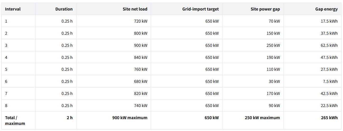
For each interval:

Summing gap power multiplied by duration gives 265 kWh. The battery also supplies 20 kWh of auxiliaries, making the illustrative event’s total AC output 285 kWh.
At the highest-load interval, 650 kW from the grid and 250 kW from the BESS serve the 900 kW site load. The BESS supplies another 10 kW to its auxiliaries, so its total AC output is 260 kW. Omitting that auxiliary demand would understate the output needed to hold the import target.
Using the same 10% allowances, design AC energy is 265 × 1.10 + 20 = 311.5 kWh, and steady-state planning power is (250 + 10) × 1.10 = 286 kW.
For a standalone peak-shaving duty, applying the previous capacity formula with the same 90%–10% SOC window, 95% discharge efficiency and 80% capacity retention gives about 512 kWh of initial nominal DC energy. This result contains no backup reservation and remains subject to the electrical compatibility and power checks described above.
If the 650 kW import limit remains active during recharge, recalculate the available charging headroom from the net site load in each recovery interval. The backup example’s 350 kW allowance cannot be carried into a different operating window without evidence.
This is one event, not an annual economic sizing result. A savings assessment requires load and billing-period data, applicable energy and demand rates, and battery characteristics, including recharge effects on billed demand (PNNL).
Check whether peak shaving and backup can share the battery
Passing each duty’s separate calculation does not establish that both can be promised from the same stored energy.
How much energy remains above the backup reserve?
For the eight-cabinet candidate, suppose normal operation allows charging to 95% SOC, while dispatch must preserve 90% SOC for backup readiness.
At 80% capacity retention, the AC energy available between those levels is:
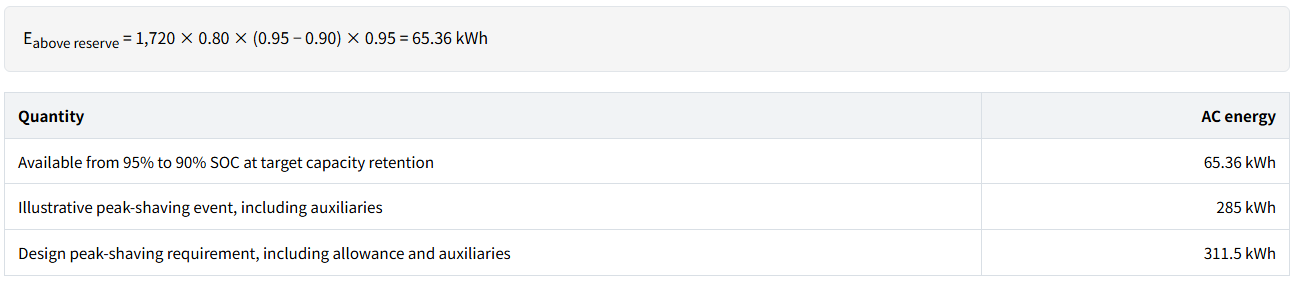
The allocated SOC window cannot complete this peak-shaving event while preserving the 90% backup readiness level. A higher PCS power rating would not resolve the energy deficit.
Even the approximately 87.26% calculated minimum starting SOC serves a different purpose from the chosen 90% readiness setting. Substituting a different dispatch floor requires recalculating what energy remains available and what backup requirement is being maintained.
Possible adjustments include more battery energy, less aggressive peak shaving, fewer backup loads, a shorter backup duration, another verified backup source, or a demonstrably available recharge opportunity. Conditional backup availability must also be described as conditional.
The EMS can enforce a feasible reserve policy. Its dispatch settings cannot supply missing energy. Reassess the allocation when load patterns, retained capacity, environmental limits or service requirements change.
Turn the results into a configuration brief for your supplier
The calculation now supports a technical discussion with explicit requirements and open checks.
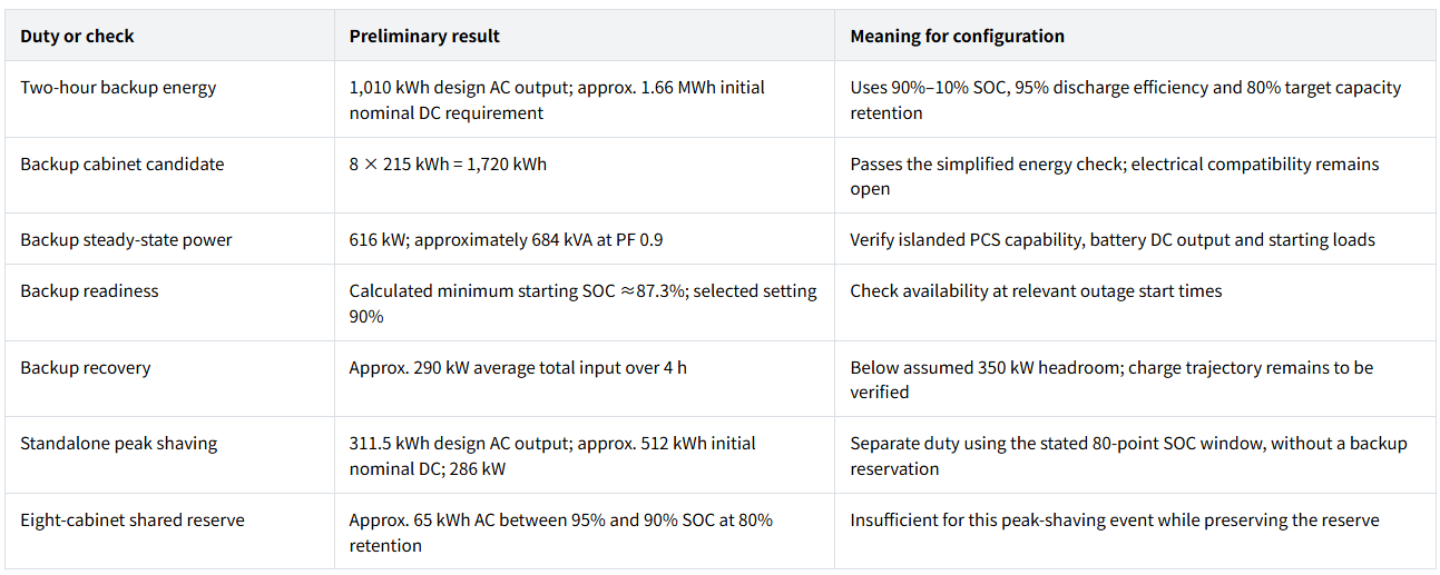
Resolve the equipment and site conditions
Before turning the candidate into an equipment order, use one configuration checklist:
- Project team — provide: load time series, critical circuits and operating sequence; maximum simultaneous running load, power factor, and starting power/current, duration, method and sequence for significant equipment.
- Project team — specify: backup duration, acceptable interruption and any black-start requirement; SOC policy, capacity-retention service point and augmentation plan; recovery window and connection headroom after other demand.
- Supplier — confirm: islanded kW/kVA, overload duration and load-step capability; battery DC power/current limits across voltage and SOC ranges; permitted cabinet arrangement and BMS–PCS–EMS interfaces.
- Supplier — document: retained-capacity guarantee conditions, temperature/altitude limits and derating, thermal-management consumption and auxiliary supply paths, commissioning and capacity-verification scope.
- Project designer and local partners — confirm: the single-line diagram and existing grid, solar, generator or other sources; site and installation constraints, target-market requirements, protection, earthing, phase imbalance and power quality.
- Project designer, supplier and local partners — confirm: grid-forming capability, transfer and continuity arrangements, black start if required, and redundancy. Include any separate UPS consumption without double-counting the same demand.
Identify missing measurements rather than filling gaps with estimates presented as facts.
Cabinet versus container selection follows the project’s equipment architecture, site and delivery conditions. The energy result alone does not determine enclosure type, and it does not establish a universal capacity threshold between them.
FAQ
Monthly bills help establish consumption and tariffs, but cannot supply the critical-load profile or motor-starting data. Obtain interval data and finer measurements or equipment information for power and starting checks. SAM cautions that scaling profiles to monthly commercial energy totals does not accurately reproduce demand peaks
No. The 1,720 kWh ÷ 800 kW = 2.15 h figure is a nominal energy-to-power ratio. Actual backup duration depends on the supplied loads, usable SOC window, retained capacity, discharge losses and auxiliaries, and requires adequate power capability.
No. The formula uses one-way discharge efficiency, relating stored-energy reduction to AC output. Charge efficiency covers the reverse path; with consistent boundaries, two 95% factors give 90.25% round-trip path efficiency. Avoid reapplying losses, SOC restrictions or auxiliary deductions already included in guaranteed efficiency or usable AC energy.
Not automatically. UPS performance depends on continuity within the loads’ interruption tolerance. Long-term off-grid supply needs generation, storage and supplementary sources to balance extended and seasonal demand. Black start is a separate ability to energize a de-energized bus without external power. NREL distinguishes UPS, off-grid and grid-connected islandable applications.
Complete the design peak-shaving duty, then immediately supply the two-hour backup duty, with no recharge. This changes the reserve policy: peak shaving may go below 90% SOC, provided enough energy remains for backup.
The preliminary requirement is about 2.05 MWh of initial nominal DC energy, exceeding the eight-cabinet candidate’s 1.72 MWh. It is an energy-only requirement and does not maintain a fixed 90% SOC floor during peak shaving. For an outage partway through shaving, use the SOC and remaining duty at that moment. Do not automatically add the duties’ 286 kW and 616 kW power figures: the grid state and supplied loads differ.
References / Sources
The external references support the methods and operating distinctions discussed in the article. The illustrative loads, numerical assumptions and calculations are specific to this worked example; they are not performance values supplied or validated by those institutions.
- GeePower — 800 kW / 1.72 MWh Solar-Storage Hybrid System in Africa. Background system scale and architecture. The calculation inputs in this article are illustrative and separate from the project’s published configuration.
- System Advisor Model (SAM) — Grid Outage. Critical-load profiles, outage timing, minimum SOC and autonomy modeling.
- System Advisor Model (SAM) — Electric Load. Hourly and subhourly load inputs, and limitations of scaling load profiles to monthly electricity consumption for commercial demand analysis.
- Emma Elgqvist, National Renewable Energy Laboratory — Battery Storage for Resilience, June 2021, NREL/TP-7A40-79850. Page 2 distinguishes UPS, off-grid and grid-connected islandable applications; page 3 discusses critical loads and outage duration.
- D. Wu, M. Kintner-Meyer, T. Yang and P. J. Balducci — Analytical Sizing Methods for Behind-the-Meter Battery Storage, Journal of Energy Storage, volume 12, 2017. DOI: 10.1016/j.est.2017.04.009. The PNNL publication abstract supports the discussion of load, tariff and battery characteristics in economic sizing.
- National Laboratory of the Rockies — Black Start. Grid-forming voltage references, restoration without external power, and transient challenges from inductive loads.